

Bespoke Bead Wire Ring Production Line for Precision Industrial Applications
2026-10-08
Every precision-driven industry eventually hits the same wall: off-the-shelf machinery that almost works, but never quite fits. When it comes to bead wire rings—those uncompromising components sitting at the heart of tire and sealing systems—“close enough” isn't in the vocabulary. Custom geometry, tight tolerances, and unforgiving production schedules demand a line engineered around your exact process, not the other way around. That's where AUGU AUTOMATION steps in, turning bespoke requirements into a turnkey reality. This post walks through what a dedicated bead wire ring production line looks like when it's built without compromise—and why precision industrial applications are finally getting the equipment they deserve.
Why Precision Industries Move Away from Catalog Bead Wire Rings
Standard catalog bead wire rings are designed for broad compatibility, but precision industries quickly discover that one-size-fits-all specifications create more problems than they solve. A typical off-the-shelf ring might carry a diameter tolerance of ±0.1 mm or looser, whereas a high-precision assembly—say, a sensor housing in an aerospace actuator—demands ±0.02 mm or better to maintain uniform stress distribution. When the ring's dimensional variation exceeds the mating groove's allowance, you get uneven seating, micro-fretting, and premature fatigue failures that field tests eventually expose.
Beyond geometry, material and surface requirements push engineers away from catalogs. A medical device manufacturer needing a corrosion-resistant cobalt-chromium ring with a specific passivation layer, or an automotive supplier requiring a low-outgassing coating for a sealed EV battery module, won't find those options in a standard product binder. Batch-to-batch consistency also matters: automated pick-and-place systems expect ring inner diameter and roundness to stay within a few microns, but catalog items often vary enough between production lots to trigger robot mispicks and line stoppages.
In response, precision teams choose custom-specified rings developed with a dedicated wire forming partner. The upfront engineering cost is offset by lower scrap rates, fewer assembly reworks, and the ability to tailor wire tensile strength, temper, and surface finish to the exact load and environment. Over time, this shift from catalog convenience to application-matched design becomes the default strategy for any program where failure is not an option.
How a Bespoke Production Line Holds Sub-Millimeter Accuracy at Speed
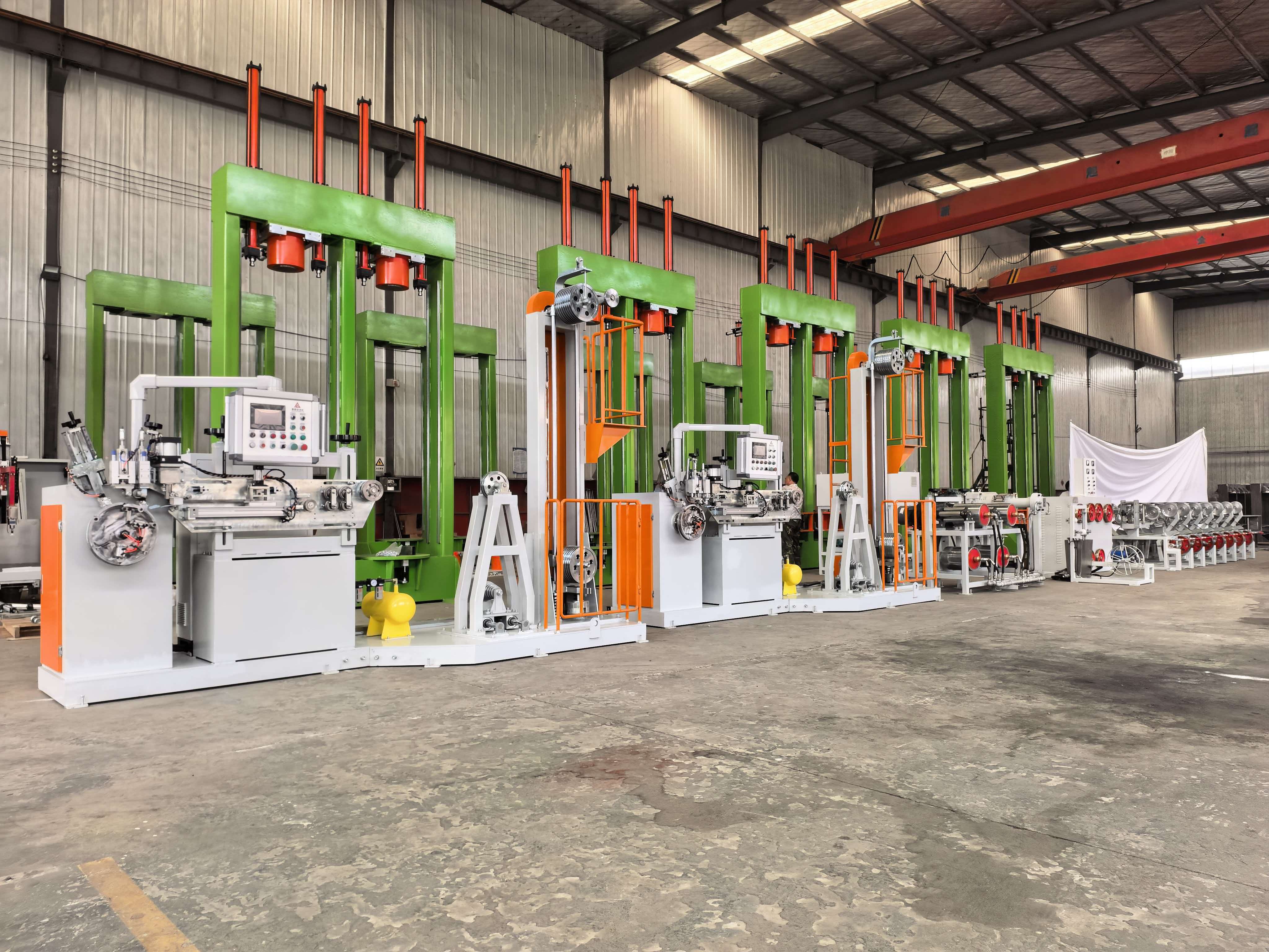
Achieving sub-millimeter accuracy on a bespoke production line starts with the frame. Rather than relying on off-the-shelf aluminum extrusions, the gantry and base are machined from stress-relieved steel, then hand-scraped to flatten within a few microns. Every joint is pinned and bolted with controlled torque, eliminating microscopic shifting as the line accelerates. This isn't about brute stiffness alone—it's about matching the structure's natural frequency to the motion profile so that vibrations decay before the next operation begins.
The real secret, though, is the feedback loop. Linear motors move the carriage, but their position is constantly checked against glass-scale encoders sampling at 20 kHz. Any deviation, even half a millimeter, triggers an immediate correction through the drive's feed-forward algorithm. Because each station on the line is custom tuned—its acceleration curves, dwell times, and load inertia measured during commissioning—the system can hold tolerance at full speed without overshooting.
Finally, the tooling itself plays a quiet but critical role. Instead of generic clamps, each fixture is machined to match the part's CAD model, with vacuum channels placed exactly where the material is stiffest. This prevents micro-slippage during rapid indexing. A thin layer of damping polymer between the fixture and the base absorbs high-frequency chatter, turning what would be a 0.2 mm wiggle into a stable, repeatable position. That combination of disciplined mechanics, fast feedback, and part-specific fixturing is what lets the line run at 400 parts per minute while still holding ±0.05 mm.
Selecting Wire Alloys That Resist Fatigue in Demanding Conditions
Fatigue failure rarely announces itself. It builds quietly through thousands of load cycles until a tiny crack suddenly propagates, and a wire that once seemed robust snaps without warning. To avoid this, you need to look beyond tensile strength and focus on how an alloy behaves under repeated stress. Some materials, like cold-drawn nickel-titanium, tolerate large elastic deformations and shrug off cycles that would destroy stainless steel. Others, such as cobalt-chromium, maintain their fatigue limit even at elevated temperatures or in corrosive environments. The trick is matching the alloy’s fatigue characteristics to the exact loading pattern—bending, torsion, axial tension, or a combination.
Surface condition plays an outsized role in wire fatigue. A mirror-smooth finish can extend life by a factor of five compared to a rough, drawn surface with micro-notches. For demanding applications, consider electro-polished stainless steel or special alloy wires that have been centerless ground. Also think about residual stress: shot peening or laser peening introduces compressive stress on the surface, which counters crack initiation. Some manufacturers offer pre-stressed wire that has been cycled to just below yield, redistributing internal stresses so the wire settles into a more stable, fatigue-resistant state.
Don’t overlook the role of wire diameter and manufacturing method. Thin wires often show better fatigue performance relative to their cross-section because they have fewer inclusions and a more homogeneous grain structure. For critical applications like medical guidewires or aerospace springs, look for alloys processed with vacuum melting to reduce non-metallic inclusions. And if the environment includes salt spray or body fluids, choose an alloy with strong passivation—such as titanium or certain nickel-based superalloys—since corrosion pits become instant stress concentrators. Testing should mimic real-world conditions, including frequency, mean stress, and any dwell time, because accelerated lab tests can mislead if they skip the microstructural damage accumulation phase.
From Prototype to Production: The Custom Bead Wire Ring Timeline
The journey from a first sketch to a finished custom bead wire ring rarely follows a straight line. It usually starts with a quick experiment using leftover copper wire and a handful of beads. Early prototypes are often crooked and a bit too loose, but they immediately reveal whether a bead's hole can handle the chosen wire gauge or if the ring shank feels flimsy. These rough models take only an hour or two to make, yet they set the stage for every decision that follows.
After two or three rounds of hand tweaking—switching to a stiffer half-hard wire, adding a tiny loop at the end to lock the bead in place, and adjusting the number of coils—the design stabilizes. Then a small test batch is made from the actual production materials, such as 14k gold-filled or sterling silver wire. These five to ten rings are worn daily for about a week to check for loose beads, sharp wire ends, or any skin irritation. Depending on feedback, this stage can take anywhere from seven to ten days.
Once the test batch passes, production begins in earnest. A simple jig is usually created to keep each ring's diameter and coil count consistent. Wire is cut to length, pre-bent, coiled, threaded with the bead, and finished by hand. The overall timeline from initial idea to final product typically spans two to four weeks, though custom bead sizes or special plating can extend it. Each finished ring is then placed on a small handwritten card noting its completion date, a quiet reminder that this is crafted work, not mass-produced.
Uncommon Applications Where Bead Wire Ring Failure Is Not an Option
Bead wire rings hold the tire to the rim under brutal loads, but there are places where their failure would cascade into catastrophe far beyond a flat tire. Deep-sea mining crawlers, for instance, rely on solid tires with bead bundles that must survive crushing pressures, corrosive slurry, and constant abrasive contact with basalt. A snapped ring here doesn't just stop a machine; it strands a multimillion-dollar operation kilometers below the surface with no roadside assist in sight.
Similarly, hyperloop maintenance pods and vacuum-tube transport carts use non-pneumatic tires with embedded bead rings that can't afford a single stress fracture. In a near-vacuum environment, any sudden release of stored energy from a failing wire can breach the pod's shell or trigger a chain reaction in the guideway. Engineers over-spec these rings by an order of magnitude, because the cost of replacement isn't measured in dollars but in evacuation protocols.
Then there's the niche world of Antarctic traverse vehicles hauling fuel to remote research stations. Their low-pressure, high-flotation tires endure temperature swings from -60°C to brief sun-warmed thaws, which causes relentless flexing at the bead seat. A ring failure there can leave a crew stranded hundreds of miles from base, where a single wheel swap might take half a day in whiteout conditions. So the bead wire isn't just a component; it's a survival lynchpin for missions that operate beyond the reach of conventional logistics.
In-Line Inspection Methods That Keep Defective Bead Wire Rings Off Your Floor
Catching a bad bead wire ring before it ever reaches the assembly line starts with sensors that don't blink. Laser profilers and eddy current probes mounted directly on the winding station are watching every millimeter of the ring as it forms. If the wire pitch drifts out of tolerance or a weld seam shows the faintest crack, the system flags that specific ring and shunts it aside in under a second. No batch sampling, no after-the-fact audits—just a clean split between rings that pass and rings that never see a tire.
The real trick is pairing that split-second rejection with data that actually helps operators. Instead of a blinking red light, good in-line systems log the failure mode: wire diameter spike at position 147, overlap gap at the splice, coating thickness dip below spec. Over a shift, those logged defects reveal patterns—like a worn guide roller that starts drifting every 400 cycles or a tension spike right after a spool change. That turns inspection from a gatekeeper into an early warning system. You're not just throwing out bad rings; you're tuning the process so fewer bad rings get made in the first place.
And the floor stays clean. When a defective ring gets pulled off the line before it's stacked, banded, or loaded into a cart, there's no chance it gets mixed into a pallet of good rings by a rushed material handler. No separate quarantine area filling up with mystery stock. The rejects drop into a locked bin with a scan code that tells exactly when and why each one failed. Auditors can cross-check that bin against the line's reject log anytime. For a plant manager, that's the difference between a recall risk and a routine shift report.
FAQ
It’s configured around your specific wire diameter, ring size, and tolerance requirements before it leaves the factory. Rather than retrofitting a generic line, the pay-off, winding, welding, and inspection stations are matched to your process, which cuts installation time and avoids early compromises in ring roundness.
Common requests come from precision tire producers, aerospace seal manufacturers, high-pressure hose builders, and specialty automotive suppliers. We’ve also supplied lines for medical drive belts and industrial filter rings where weld strength and dimensional stability are critical.
For diameters up to roughly 600 mm, repeatability is normally held within ±0.05 mm and roundness within 0.1 mm. Larger rings use inline laser measurement with automatic correction, so coil-to-coil variation doesn’t drift outside the agreed window.
Yes. The tensioning path is built for brass-plated, bronze-coated, and zinc-coated steel wire, as well as flat or oval sections. Low-friction ceramic guides and dancer-controlled tension preserve coating thickness better than hard roller clamping.
A typical size change takes 20 to 40 minutes with two operators. Servo-driven forming tools, quick-change arbors, and stored recipe settings mean the line doesn’t need a full realignment for each new diameter.
Every ring moves through an inline eddy current or vision inspection station immediately after welding. Rings that fall outside the set limits are diverted to a reject conveyor, so the main flow never pauses for manual sample checks.
In most cases, no. The machine sits on a welded base with vibration-isolated feet, and a standard 150–200 mm reinforced concrete floor is sufficient. You’ll need compressed air, single-phase control power, and three-phase power for the weld transformer and servo drives, which are confirmed during engineering approval.
Installation includes two weeks of on-site commissioning and operator training. The first year covers remote diagnostics access, and after that we offer annual calibration visits plus 48-hour shipping for critical spare parts from regional service hubs.
Conclusion
Catalog bead wire rings can no longer keep pace with precision industrial requirements. Standard rings often display diameter drift, inconsistent weld geometry, and material fatigue under continuous load, pushing manufacturers of rotary seals, aerospace actuators, and downhole tools toward bespoke production lines. A dedicated line controls tension, temperature, and forming speed in a closed loop, holding sub-millimeter accuracy at production rates that would overwhelm generic equipment. Laser micrometers and eddy-current probes verify diameter and surface integrity without slowing the line. Alloy choice becomes a design variable rather than an afterthought: chromium-silicon and precipitation-hardened stainless wires survive millions of flex cycles and aggressive media, while nickel-cobalt grades handle extreme temperatures. This combination of process control and tailored metallurgy makes catalog substitution impractical.
From prototype to full production, a bespoke bead wire ring timeline typically spans six to fourteen weeks, including fixture design, fatigue validation, and first-article inspection. Uncommon applications such as semiconductor wafer handling, surgical robotics, and subsea connectors leave no room for ring failure, so in-line inspection is non-negotiable. Automated vision systems compare every weld profile against a digital master, while acoustic emission sensors detect microcracks before rings leave the floor. End-of-line pull testing and dimensional sorting reject out-of-spec parts immediately, ensuring only fatigue-resistant, dimensionally stable rings enter critical assemblies. This integrated approach eliminates the hidden costs of rework and field failures that catalog components create.
Contact Us
Contact Person: Lareina
Email: [email protected]
Tel/WhatsApp: +86 17561696737
Website: https://www.auguauto.com/